As proof there is always something more to discuss in carburetor tuning, reader Jim Mosher commented that I left out of my “How to Tune Carburetors” story any discussion of the needle jet size as an element in carb tuning, and he is quite right.
Back in 1971 when I was race tuning two-strokes, I learned something about needle jet effects from accomplished tuner and parts-maker Harry Hunt. He started the conversation by noting that there is some variation in the dimensions of carb tuning parts, such that it can be well worthwhile to try some variation, plus and minus, just to be sure where we are. Without coming right out and saying “Do this” he implied that needle jets were an underused resource.
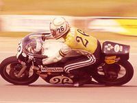
Early the next season my rider Cliff Carr and I trucked our 250 up to Loudon, New Hampshire, for a tuning day. I brought along a range of needle jets to explore the point Hunt had made.
Carr went out and did a few laps for baseline, and we began trying needle jets other than what came in the bike. He’d do five timed laps, come in, and we’d discuss how the bike had performed. Just when it seemed that we might as well have been trying various stiffnesses of seat padding, here came a group of five laps that were four-tenths of a second faster on average than previous.
As Carr rolled in the pit road I made an effort to smooth out my face and look bored.
“How was that?” I asked in a neutral voice.
“Seemed kinda…flat,” was his reply.
“Okay, how about this?” I said, giving him the stopwatch board. His eyebrows went up.
Four-tenths seems pretty insignificant by itself, but do that for 15 laps and it adds up to reaching the finish line six seconds sooner.
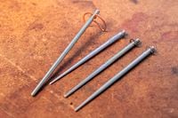
Mr. Mosher notes that the first 20mm of the jet needle are not tapered at all; they are cylindrical. So changing the diameter of the needle jet gives control over mixture during initial slide lift—control that is independent of the control given by varying throttle slide cutaway.
When Cliff described the engine as “kinda flat” it may have been just that. If a carburetion change smooths out power delivery, it becomes comfortable to use more of it, and the laps become faster.
On the accompanying graph, I have put throttle slide lift in millimeters (mm) on the y (vertical) axis, and fuel delivery orifice area (area of needle jet minus area of needle at that slide lift) on the x (horizontal) axis.
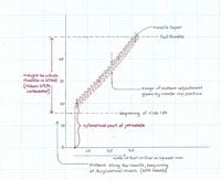
Note that there is no change in fuel orifice area during initial slide lift. That is because it is the cylindrical part of the needle that is in the needle jet.
After that, it is the taper of the needle that is in the needle jet, so the fuel orifice area begins to increase on a slope, upward and to the right.
Raising or lowering of the needle just raises and lowers the sloping line, making fueling richer or leaner “on the needle,” which is from roughly 1/4 to 3/4 of throttle slide lift.
/cloudfront-us-east-1.images.arcpublishing.com/octane/N575KB7BDZDPPJBRLZRG2ANHKI.jpg)
/cloudfront-us-east-1.images.arcpublishing.com/octane/T77HXRXV4NGKDNZODMSEIBRXPE.jpg)
/cloudfront-us-east-1.images.arcpublishing.com/octane/NKMM7V2P3BCSXAV6J56FKK67OU.jpg)
/cloudfront-us-east-1.images.arcpublishing.com/octane/SWQRQV27DNFA7LXGFI7FNFNGOQ.jpg)
/cloudfront-us-east-1.images.arcpublishing.com/octane/GYEXUJBV5JGQLLZNXO7KRVSTEY.jpg)
/cloudfront-us-east-1.images.arcpublishing.com/octane/MCWUSJJVJVG45P7QQG3WOXZR54.jpg)
/cloudfront-us-east-1.images.arcpublishing.com/octane/AJ4EFPH2CRDURDAB5LPEA2V2NE.jpg)
/cloudfront-us-east-1.images.arcpublishing.com/octane/LSDHIL22SZAFFPYLKP5ZXLJSIY.jpg)
/cloudfront-us-east-1.images.arcpublishing.com/octane/SH46HIOX4RELXLXF6AE3SFGH4A.jpg)
/cloudfront-us-east-1.images.arcpublishing.com/octane/JUZ52WFWLJGMNH7PGZNOKP3MUY.jpg)